Static Corrections
Before carrying out the NMO correction it is usually necessary to perform a static correction, which amounts to moving the entire seismic trace up or down in time.
There are two main reasons for applying static corrections.
Put shots and receivers on a flat datum plane.
Correct for near surface velocity anomalies beneath the source or receiver.
Elevation Statics

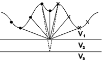
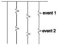
Consider the need for (1). Common midpoint shot receiver pairs acquire data on an irregular interface (right figures, top panel). Time differences are caused because of extra travel time associated with elevation of source and receiver. As a result reflections observed on the CMP gather will not have a hyperbolic form and they will not be amenable to normal CMP processing (bottom panel).

The correction procedure involves establishing a datum on which to locate source and receiver, and then adding or subtracting the incremental time. The reference velocity will be that of the upper layer.

The reflections of interest are usually coming from great depth and the upcoming energy is traveling nearly vertical. So the static correction due to elevation expressed as a change in travel time is
and is subtracted from the record. That is, the whole seismic record is shifted in time by a value \(\Delta t\).
After static correction, the subsurface events will look more like an hyperbola and they will be ready for velocity analysis, NMO and stacking.
Near-surface velocity anomalies

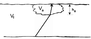
Similar bulk shifts in time will occur if there is anomalous velocity beneath a source or receiver or if the thickness of the weathering layer changes substantially. The amount to be subtracted from the seismic trace time is given by the following formula:
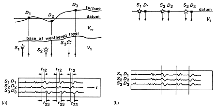
The first layer is often highly weathered and it has variable thickness and velocity. It is also usually poorly consolidated and therefore is a poor transmitter of seismic energy. In exploration it is common to drill through the weathered zone into the upper layer. Drill measurements establish the thickness at the shot. By having a seismometer at the surface above the shot one can estimate the velocity of the weathered zone. The diagram below [1] shows the differences between reflection events on adjacent seismograms due to the different elevations of shots and detectors and the presence of a weathered layer. After static corrections the seismograms should show better alignment of reflection events.
