High power and reliable constant current are the primary requirements. For
small scale work, transmitters capable of sourcing up to several hundred
milliwatts of power might be adequate. For larger scale work, it is possible
to obtain transmitters that can source up to 30,000 watts. Current is usually
injected as a 50% duty cycle reversing square wave; that is, current is on for
several seconds, off for several seconds, on with reversed polarity, off, etc.
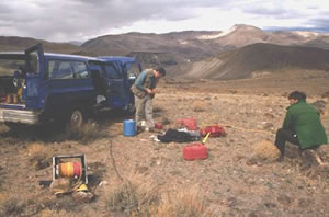
Fig. 182 Sorting wire and equipment to begin a resistivity / IP survey for a
mineral exploration target. The survey lines will be up to 2 kilometers
long. Transmitter wire is on a back portable reel, and wiring for reading
potentials is bundled around cans for generator fuel and water for the
crew of 4 field operators.
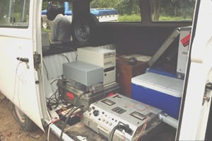
Fig. 183 A small transmitter for mineral exploration (2500 watts) sitting on the
floor of the field van. A full-waveform receiving system’s electronics and
computer sit just behind. Power is supplied by portable generators placed
some distance from the vehicle to minimize the noise. (Midaas PCIP survey
systems, 1994.)
Decay voltages in IP surveys (measured during a time domain transmitter’s
“off” stages) are often two orders of magnitude smaller than primary voltages.
Therefore, very high-power transmitters are often desirable. For mineral
exploration in conductive ground (where potentials will be small), it is
possible to obtain transmitters capable of sourcing tens of kilowatts of
power. Needless to say, these are rather dangerous systems, and definitely not
portable! The figures below show several currently available transmitters.
Fig. 184 Three transmitters and their power generators.Images are from Zong
Engineering and Research sales literature.
Fig. 185 0 kW Scintrex resistivity-IP transmitter in use in the field. The power
generator is on the pickup truck.
For DC resistivity sounding, a simple digital volt meter can be adequate. A
more complex system may involve amplifiers, filters, transmitter synchronizing
circuits, display, storage, many inputs for simultaneous recording of many
potentials, and other features. Synchronization with the transmitter is
essential if IP data are to be gathered, but it is not critical if resistivity
information only is to be obtained. IP receivers also must be capable of
recording several signal strengths covering several orders of magnitude
because signals while the transmitter is on may be several volts, while decay
voltages during the transmitter’s “off” time may be only a few micro or
millivolts.
In general, current injection and potential measurement electrodes are not
interchangeable. However, automated acquisition systems using smaller source
currents do employ the same stainless steel electrodes, both for sourcing
current and measuring potentials. This becomes more and more difficult as
source currents increase because the ground can become altered by high current
densities.
For injecting current, low impedance is required, i.e. good contact resistance
is the primary concern. Stainless steel stakes, sheets of foil, wetted (and
perhaps salted) ground, are all possible approaches to improving contact
resistance.
For measuring potentials, low noise, non-polarizing (not necessarily low
impedance) electrodes are the primary concern. Small lead plates buried in the
soil will often do the trick. In more difficult situations, wet electrodes
made from porous ceramic jars containing copper sulfate solution are required.
See Corwin, 1990 for a good discussion of electrodes for this type of galvanic
work.
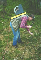
Fig. 186 Ordinary insulated wire on reels (possibly on a back-pack) for easy
handling are most common (figure to the right).
For small scale work, some systems are available that use multiconductor cable, and possibly “smart” electrodes that can be switched between input and measurement functions by computer.
For large scale work, this is not practical because of the large currents involved (up to a hundred Amps or so in some cases). Multiconductor cables with individual wires capable of carrying that current would be prohibitively heavy for mineral exploration surveys, which commonly involve profile lines several kilometers long.
However, there are some systems that use multiconductor seismic cable for the potentials while requiring the normal single, heavy gauge wire for the current source.
Since the early 1990’s manufacturers of instruments have been producing
automated systems which permit the use of electrodes for either current source
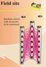
or potential measurements. Some systems involve planting a series of
electrodes and wiring them together with a cable, which allows each electrode
to be selected either as a potential electrode or as a current source. This
procedure is being implemented in borehole projects, as well as surface
surveys. Examples of systems that work in this manner are given in the
following list (as of January 2007).
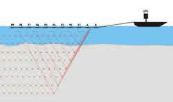
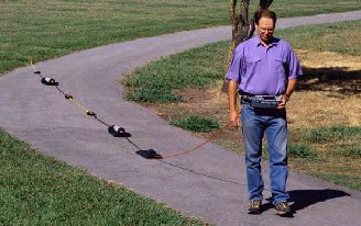
Another arrangement involves a towed array system in which all potential and
source electrodes are basically heavy metallic weights. This arrangement is
efficient when the survey site is essentially flat and ground is relatively
soft. Other similar systems used both for land and marine use use capacitively
coupled electrodes rather than electrodes that make galvanic (direct) contact
with earth materials. One example of this approach can be seen at at the
Geometrics (image to the right) website (as of
January 2007), and others.
In the early 1990’s receivers were developed that could record complete
digitized potential waveforms rather than simply measuring voltages at
specific times relative to the transmitted signal. These systems produce large
data sets, but with field computers running the systems, storage is not a
problem. Fully digitized waveforms have several potential advantages,
including identification and removal of all types of noise, and interpretation
of subtle, 2nd and 3rd order effects caused by frequency dependent responses
of subsurface materials. One example of a current full waveform system is the
Titan 24 Deep Earth Imaging System of Quantec Geoscience (as of January 2007).
An example of full waveform data gathered by MIDAAS Inc. in the early 1990’s
is shown to the right. The figure shows the “off-time” IP signals for 12
potential measurements taken using one current station. “On-time” signals are
not shown.
Corwin, R.F., 1990, The self-potential method for environmental and engineering applications, in Geotechnical and Environmental Geophysics, Vol I: Review and Tutorial, (Ward, S.H., ed), Society of Exploration Geophysics, pg 127 - 146.