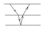
Lateral Velocity Changes
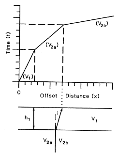
The headwave travels at the speed of the underlying medium and that velocity might vary laterally. This produces another complication when interpreting the first arrivals. Consider the two velocity models and traveltime curves given below. The traveltime curves are the same. We note that the crossover point between \(v_{2a}\) and \(v_{2b}\) in (b) is always shifted away from the shotpoint with respect to the location of the position of the subsurface change.
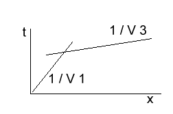
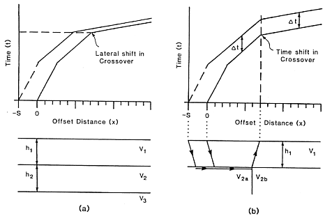
To determine which structure is correct we need another shot. It could be a reversed shot, or a shot that is off the end of the profile. If the shot is offset then the travel times from the two velocities are shifted as indicated below. In (a) the traveltime curve is shifted to the left by an amount \(S\). In (b) a constant time increment is added to each arrival and the location of the crossover remains the same.
Phantoming
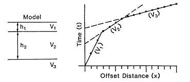
As shown in the above diagram, refracting arrivals from two shots from the same end produce traveltime curves which are parallel. This provides a good way to group first-break arrivals according to specific refractors. Ideally we want to have many arrivals from a single interface. This can be accomplished by using the parallelism noted above and phantoming the arrivals. That is, we can determine the arrival time of the refracted event at a location where no seismometer really existed. Phantoming can be carried out in the cases where:
The receiver array is fixed, and off-end shots are recorded.
The shot and receiver array is moved.
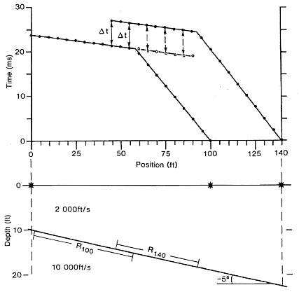
The diagram here shows an example where the spread is moved.
For the shot at x-position 140 feet , data from the shot at 100 feet can fill in arrival times between positions 0 and 40 feet.
For the shot at 100 feet, data from 140 can phantom in artificial arrivals that arrive before \(x_{crit}\). The data can help define the intercept time because we now have more points to help estimate a straight line. Note that these phantomed values don’t actually exist but they are valid data for helping us estimate the slope and intercept for the particular refractor.
Static Data Corrections
There are two corrections that are sometimes applied to the recorded travel times. These are corrections for elevations and similar corrections when there is a known weathered layer which has variable velocity.
Elevation Correction: The goal is to reduce the data to a datum plane, that is, to define a flat surface on which the data might have been recorded. The importance of this lies in the fact that all of our interpretation formulae assume that the upper surface of the earth is flat. Let \(h_S\) and \(h_D\) respectively denote the height of the shot and receiver about the datum plane (negative heights are allowed). The angle that the waves in this region are travelling upward or downward is determined by Snell’s law. If \(v_n\) denotes the velocity of the refractor then the elevation correction is