Receivers
A seismic detector measures the displacement, velocity or acceleration of material. Typically it is an electromechanical device that responds to a mechanical input such as physical motion or pressure, and outputs an electrical signal.
On land the instruments are called seismometers or geophones. Once the sensor’s spike (right) is planted into the ground, the geophone case moves with the ground while a heavy magnetic mass suspended on a spring inside the case stays stationary owing to its own inertia. The relative motion between a coil wrapped around the magnet, and the magnetic field supplied by magnets attached to the case, sets up a voltage in the coil. This voltage is passed along the wire to the recorder where it is converted to a digital signal and stored.
Geophones are sensitive to motion only along the axis of the coil. Vertical ground motion is best detected by a orienting the coil vertically to build a vertical geophone. It is also possible to mount the spring/mass system horizontally. A combination of several sensors in different orientations allows ground motion in all three directions to be measured.
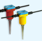
Fig. 67 Land Geophone
Seismic signal detectors for water-borne deployment are called hydrophones. These are generally ceramic piezoelectric elements which produce an output voltage proportional to the pressure variations associated with the passage of a compressional wave through the water. At sea, these are often carried in a neutrally buoyant cable (seismic streamer). Recall that shear waves can not travel in liquids.
Recording equipment
Seismic data consists of records of ground motion at each geophone location. Each record shows how ground moved as a function of time, starting at the moment the source energy was generated. The records are usually a few hundred milliseconds long, and are digitized (ie sampled) at a sampling rate of perhaps several samples per millisecond. This is not very different from the sampling rate for digitized music. Therefore, recording equipment must have the following capabilities:
An analogue to digital number converter that converts the measured electrical signal into a time series of numbers.
A synchronizing facility so that digitizing can start at the same time as energy is initiated at the source.
A computer to manage the input from the geophones.
The computer must be able to “replay” or plot the seismograms (signals from each geophone) so that data quality can be checked visually. Old units had a small strip-paper printer.
Since there is a computer, most systems include built in software to carry out initial interpretations of refraction data.
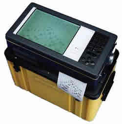
Fig. 68 “SmartSeis” seismograph which can record up to 24 channels, manufactured by Geometrics. A good place to see specifications of engineering scale seismic equipment is https://terraplus.ca/sale/seismic (Terraplus is an equipment rental company, based out of Richmond Hill, Ontario).
Below is an image showing simulated exploration of Mars at the Haughton-Mars Project, an international, interdisciplinary field research project. The “Mars analogue” field site is in the Haughton crater, a meteorite impact crater, on Devon Island in Canada’s high arctic. A line of geophones is being planted, the seismograph is nearby. The goal is to characterize the layered structure under the field site.
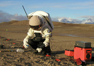
Fig. 69 Installing a seismometer on mars! :)